The Atari primal rage cabinet featured Atari CAGE: Total Immersion Audio. This meant it had 4″ stereo speakers above the screen and a sub-woofer in the lower cabinet next to the coin doors. This was intended to give games more impact with the extra dynamic sound. That being said, since I was working with an empty cabinet, it did not have a CAGE chip and amplifier, only the speakers.
This cabinet was fairly massive, as it originally had a full size CRT in it. Arcade purists will say its the only way to go to get the “feel” of an arcade game. That being said, I’m trying to make this monster lighter, and thinner. I have no problem putting a midrange LCD screen in the cabinet, it runs cooler, and takes far less power. The monitor install will be covered later, lets check out the cabinet. The cabinet was originally 25″w and 38″d (from the back to the edge of the control panel). It was nearly impossible to get down the stairs to the cave. I marked the cabinet off around the back, removing about 10 inches.
This is the first post of many, I’m building a chronicle of a conversion of a 1994 Atari Primal Rage cabinet into a slimline Multi-Arcade Machine Emulator (MAME) cabinet.
A few months ago I took my old project, a restored 1977 Bally Eight Ball pinball machine to a collector and restorer downtown.
I traded him for various parts and pieces, and a full size slant-back cabinet with no monitor. As it sat, it was currently configured as a “Big Buck Huntin'” lightgun setup.
My buddy and I were woefully unprepared for how heavy the cabinet was. Alas, we stripped the gun from the unit and loaded it up.
Upon arriving in the shop and further inspection, I discovered it was originally born an Atari Primal Rage machine, built sometime in 1994.
This cabinet features a steeply slanted top-back section, making it ideal for a slimline cabinet, as the slant will allow for attic ceiling installation.
My studio is in my attic, so it’s final location plays a large part in the project.
The machine was in my dining room for the first few nights until I could clear space in the shop.
My wife was fairly unhappy about it being in the living room, and it did have a very interesting smell considering years of storage in bars/arcades.
I couldn’t resist tearing stickers off, and throwing an old PC on the tray and testing it.
So today, I had some time to do repairs so I heated up the soldering iron and jumped in.
The dead flipper was my first task.
This is pretty charred.
The underside of the flipper assembly. I thought for sure this solenoid was dead, as it looked burnt.
I went thru pulling it off the play field and noticed that the ground wire had snapped off at some point. I cleared some insulation from the wire and connected it again, flipper moved. So I soldered it and now I have an extra flipper solenoid for the future. Also, the new flipper is slightly thinner in design…
Close enough for now.
I ordered new rubber pieces for the whole game as they were very dried and rotten.
The “Pinky Kicker” without the shield
Here is a kicker switch with the cover removed. I had to adjust the bump switches on either side of the kicker leg. Notice the rectangle piece of metal that is outside of the rubber ring? That had to move to the inside of the kicker assembly. Now when a ball hits any piece of that leading rubber edge, the ball gets launched away by the kicker.
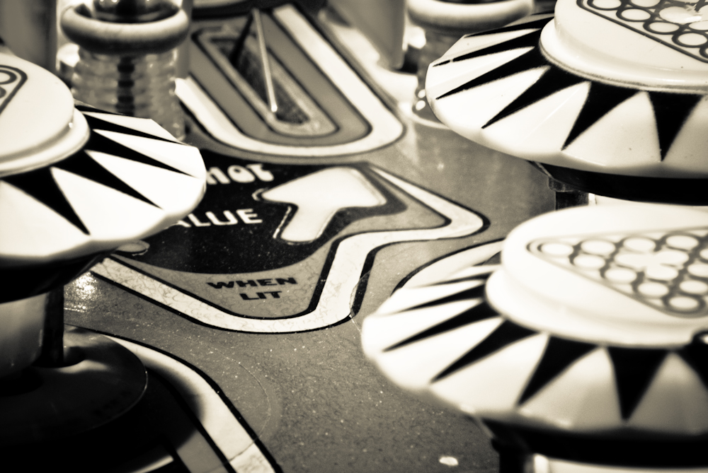
Here’s the play field with new rubber.
More Rubbery than before.
The machine’s sounds are produced by an electro-mechanical chime box.
I noticed that there were 4 chimes that play “call to the post” when you hit the start button. The lowest key never plays.
This solenoid controls the lowest note on the chime box. It was so fried that the inside of the shaft expanded and caused the plunger to bind. I’ll need to order one of these.
The backbox was where I found the first fried circuits. Its basically the brain of the machine.
Inside the backbox
These boards control Lighting, Processing and Memory, Electrical Routing, and Switch/Solenoid operation. This is what’s behind the scoreboard.
After I did this maintenance, The game was repaired enough to play it. I had to adjust a few switches and things to work out the kinks, but now it basically works.
I have a few more issues to deal with that I’m going to have to wait to get to:
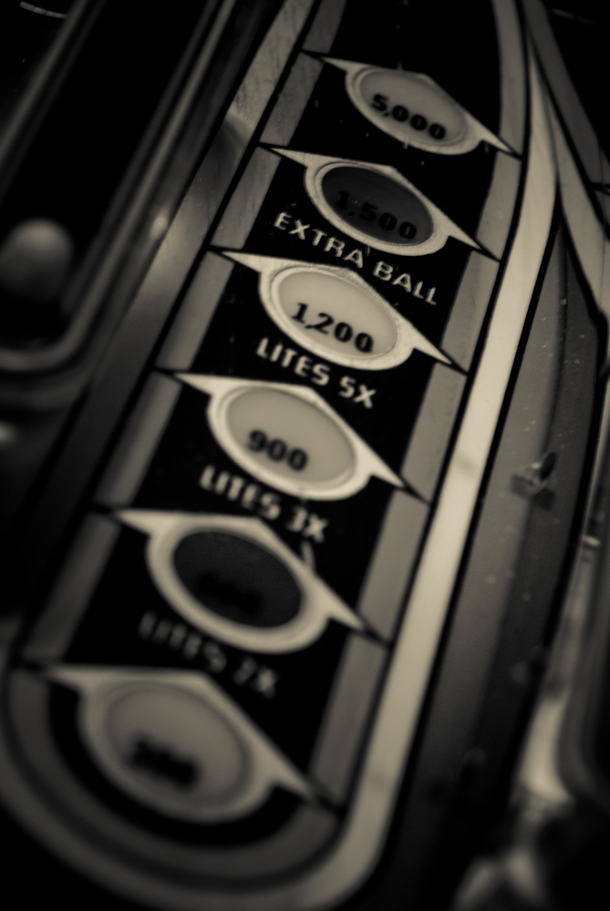
The “Ball Display” needs cleaned inside the lenses. There is dirt and soot under these lenses from the lights burning. It should clean up with some alcohol.
There’s a weak capacitor somewhere, as when the bumpers are hit the lights on the game dim. It could also be fixed by replacing the #45 lights with #47 as they are far more efficient.
The plasma in the scoreboard flickers.
Behind the scenes
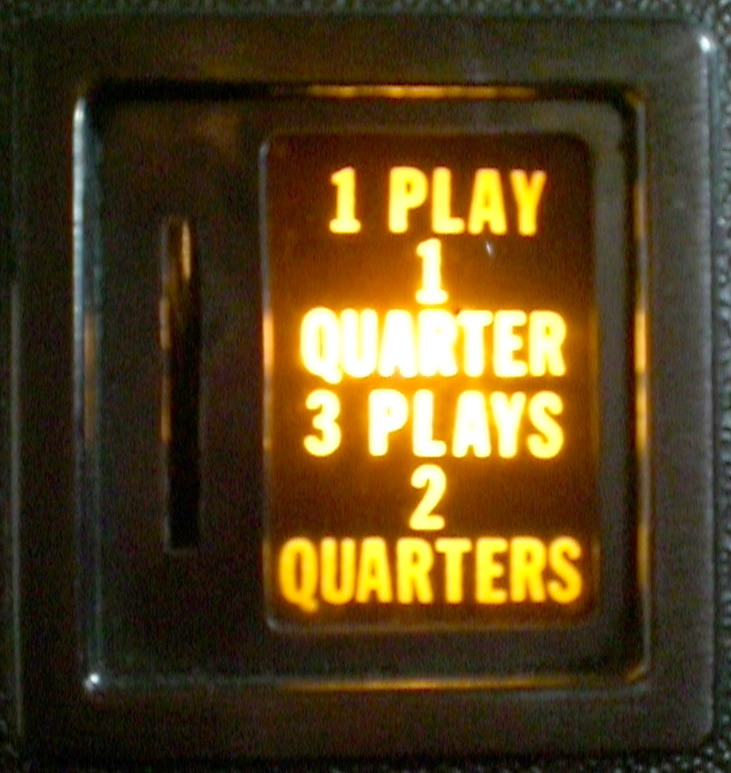
Also, if you put 1 quarter in, you’re supposed to get 1 credit. Right now it gives you 20. When I was a kid at the arcade, I would have killed for that ability.
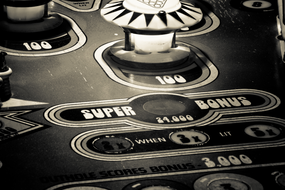
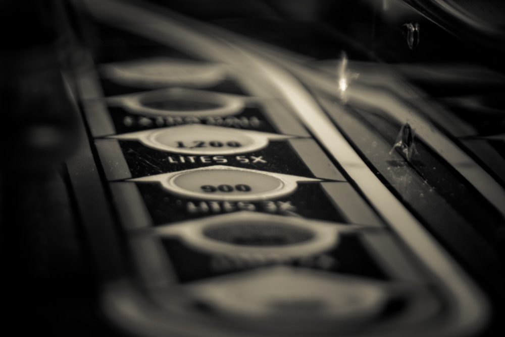
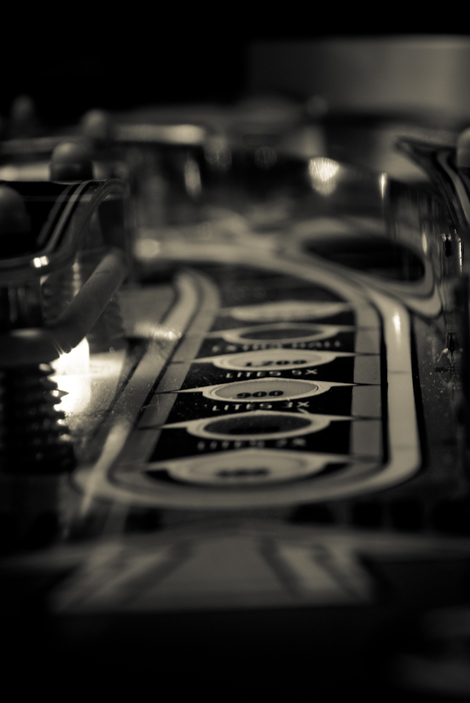
Here, I took some detail photos to show off some of the design elements of the game. Sometime soon I’ll have a proper shoot with a better camera. I promise.
You should be able to click on any image, or just page thru the gallery in the light box.
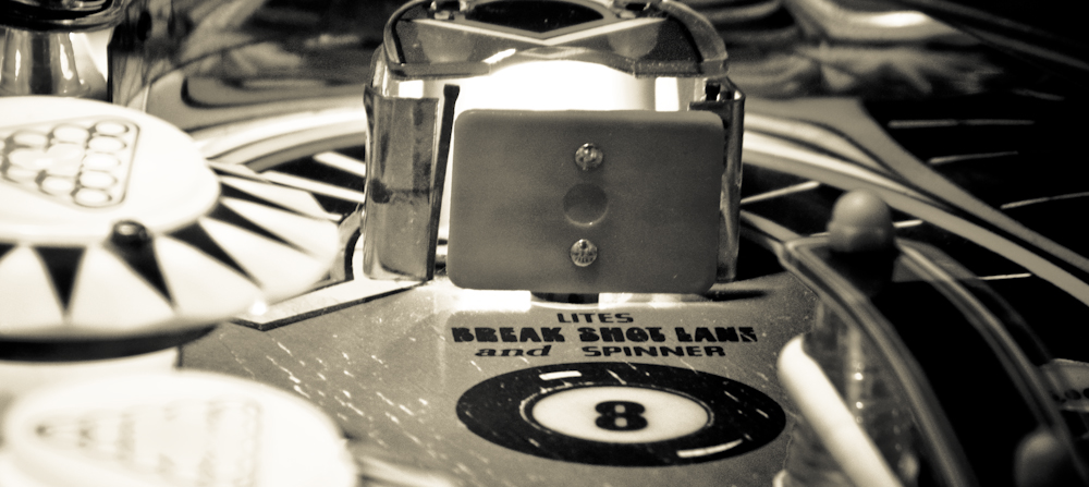
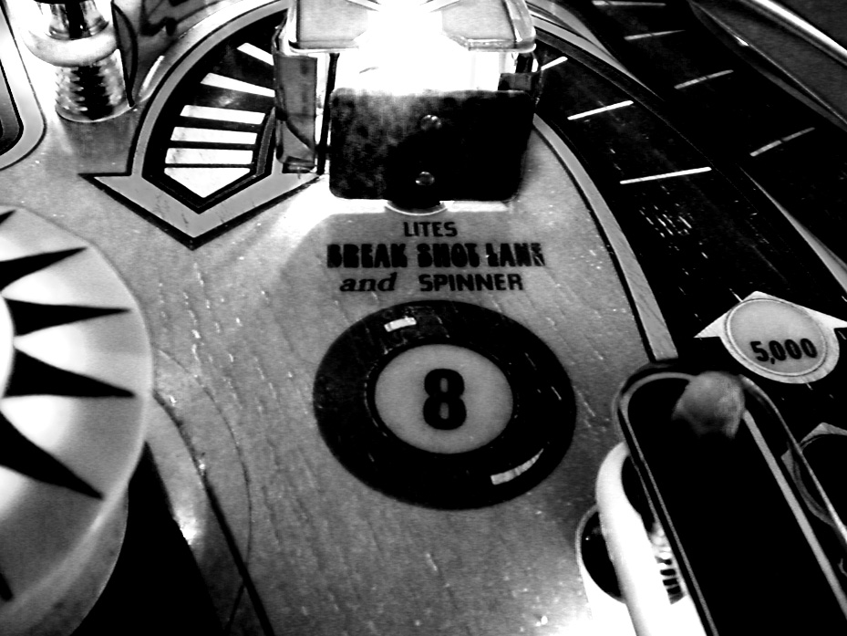
This is the target to activate the Eight Ball
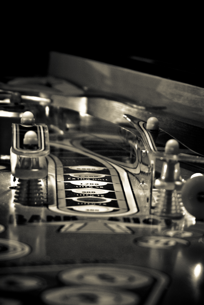
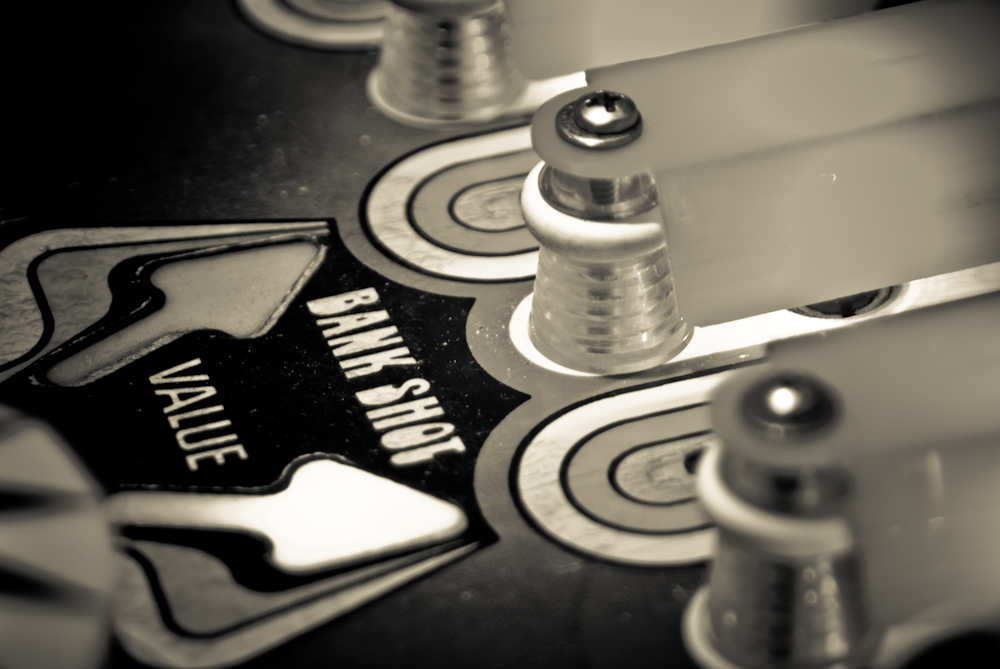
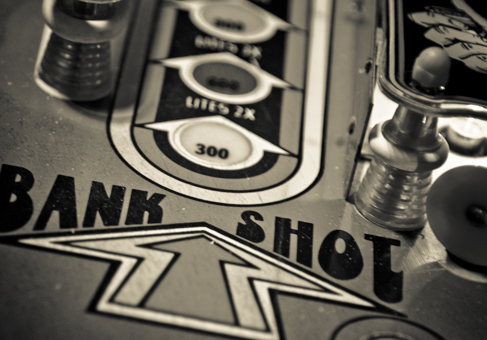
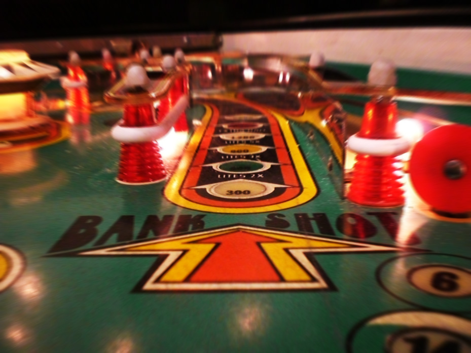
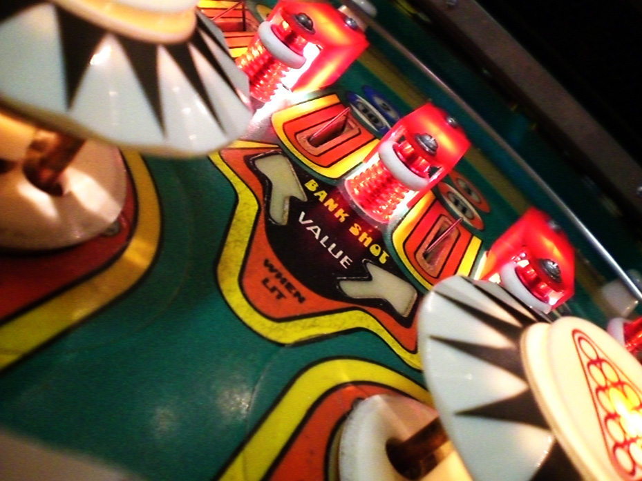
Up into the bank shot slingshot.
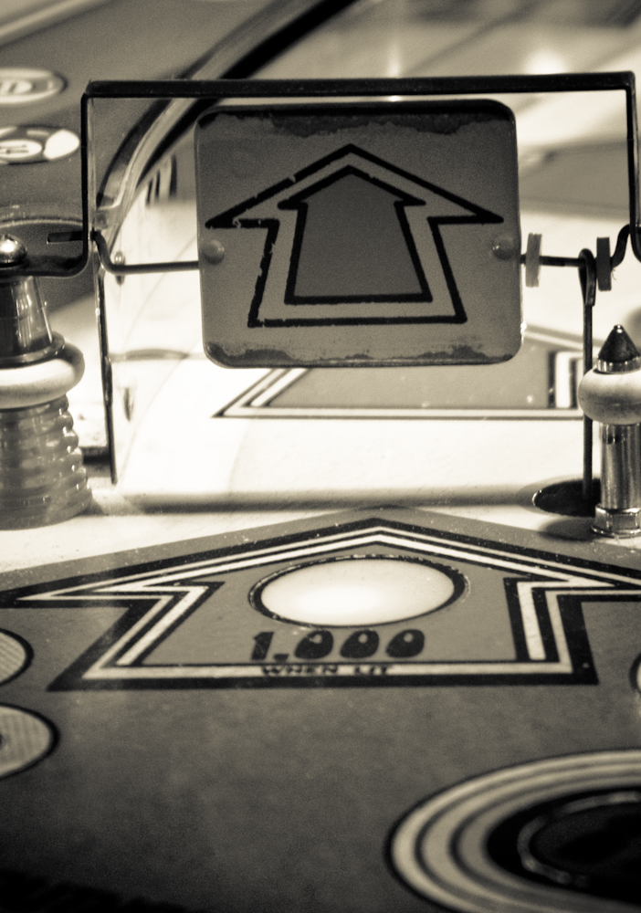
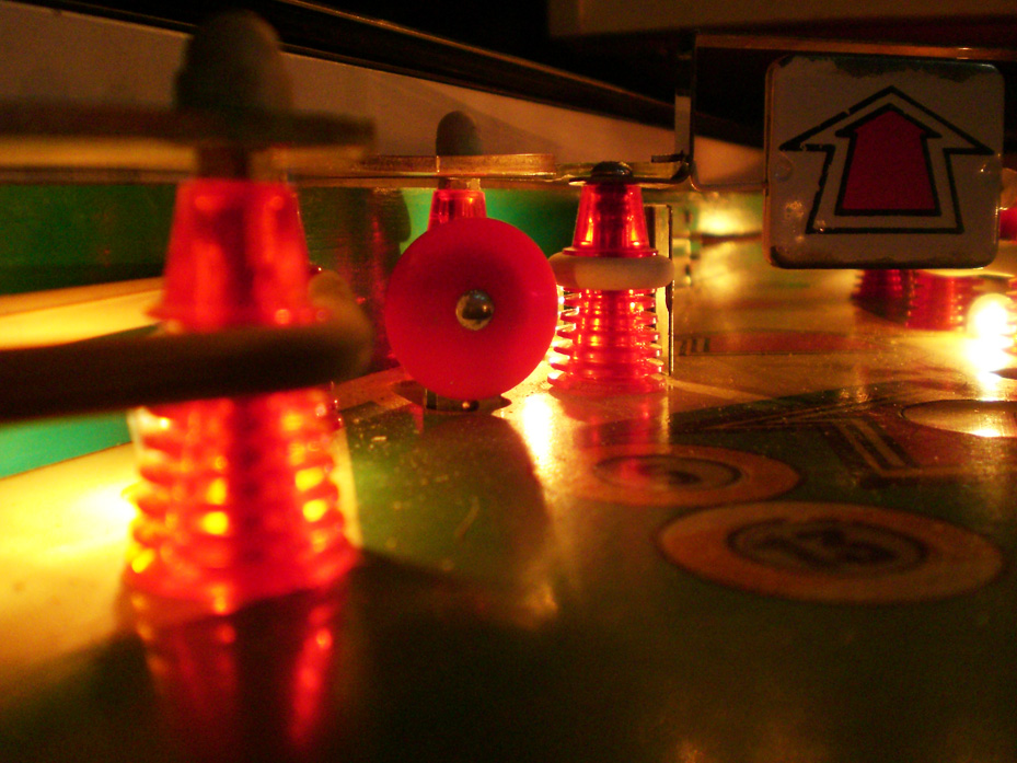
A pinball’s eye view of the lead bumper in the field.
Prices like this are a thing of the past, for sure.
Interesting facts from the Internet Pinball Database.
Side Art Picture from ipdb.org
Manufacturer: Bally Manufacturing Corporation (1931-1983)
Project Date: January 17, 1977
Date Of Manufacture: February 21, 1977
Model Number: 1118-E
Production: 20,230 units (confirmed)
Notable Features: Flippers (2), Pop Bumpers (3), Slingshots (2), Stand up targets (4), Roll under spinner (1), Left out lane kickback.
Illuminated Bumpers Picture from ipdb.org
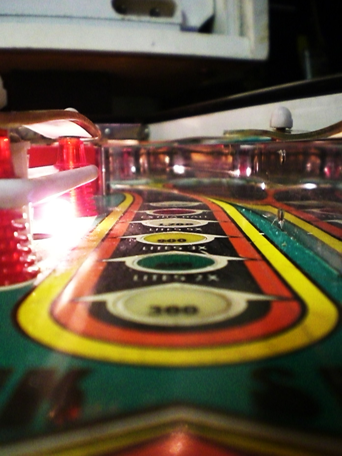
Lanes Picture from ipdb.org
Maximum displayed point score is 999,990 points per player.
Bank Shot Picture from ipdb.org
Design by: George Christian
Art by: Paul Faris
Although Eight Ball is a solid state machine, sound is not generated by a sound board. Instead, a 4-note MPU controlled chime box produces the sound for this game.
Chime Box Picture from ipdb.org
This provides the experience of solid state scoring and response, with the added nostalgia of Electro-mechanical chimes.
The BONUS BALLS in the center of the lower play field are designated balls 1-7 for Players 1 & 3, balls 9-15 for Players 2 & 4.
Artist Margaret Hudson, who assisted Paul Faris on this game as a learning experience, says those are her initials on the bracelet of the girl in the back glass.
Back Glass Picture from ipdb.org
Two of the light shields are unusual as they have a second screening of red on top of the normal screening. This causes an effect similar used on the “Phantom of the Opera” glass, though no one probably would ever normally notice. For instance, “Pinky Tuscadero’s” shirt on the slingshot plastic appears red when the game is on, and tan when it’s off.
The representation of Henry Winkler’s Fonzie character from the TV show Happy Days in the artwork was not licensed and caused a problem after it was released.